Short answer
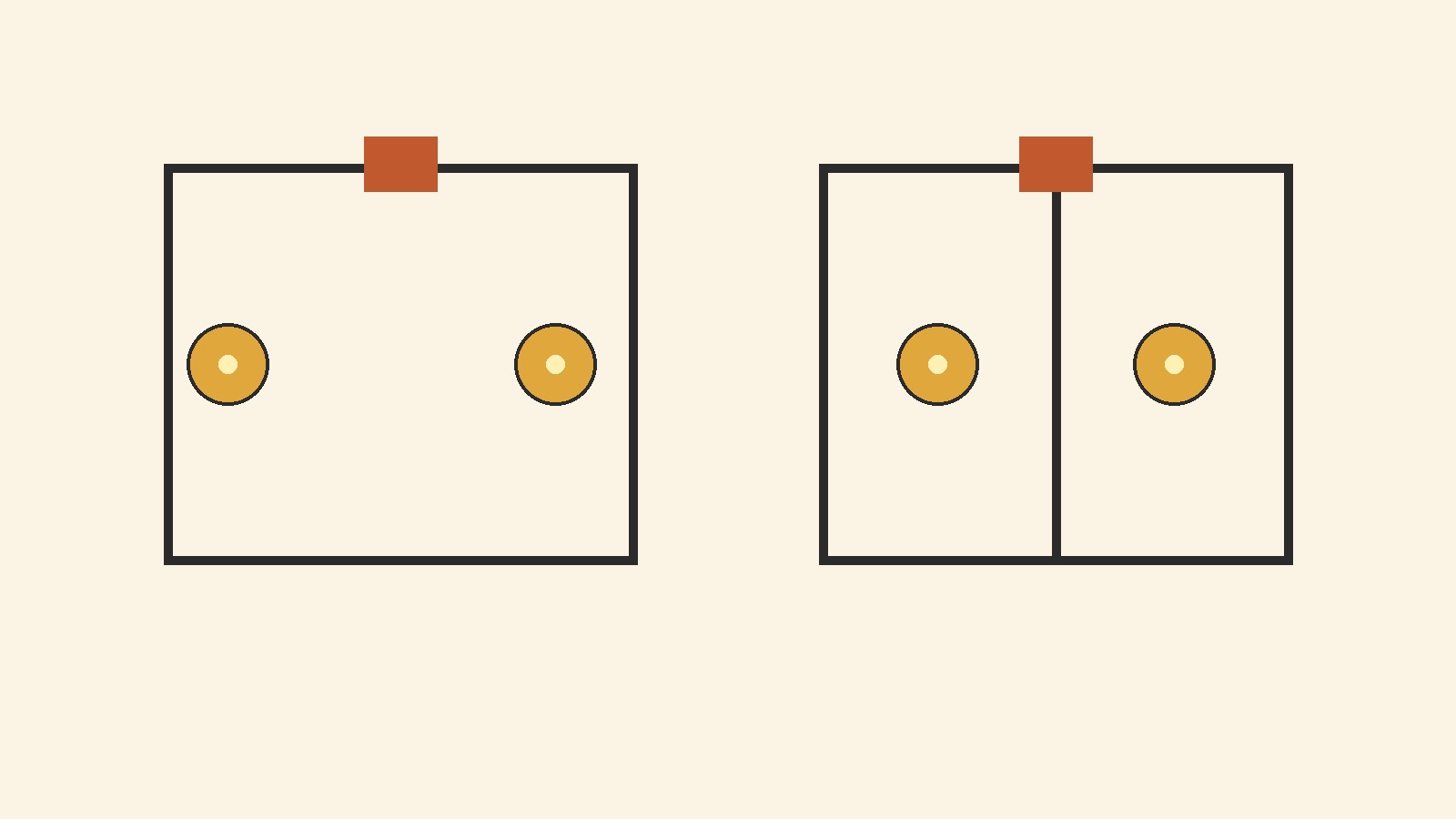
- In a series circuit, components are connected end to end in one path. The same current flows through every component, the supply voltage is shared among them, and if one component breaks the path, current stops throughout that loop.
- In a parallel circuit, components are connected on separate branches across the same supply. Each branch gets the full supply voltage, the total current is the sum of the branch currents, and one branch can stop while the others keep working.
- For resistors, series resistance adds directly. Parallel resistance follows the reciprocal rule, so the total is smaller than the smallest branch resistance.
- Most real circuits are combinations. Reduce one clear series or parallel group at a time, then check that voltages add up in a loop and currents add up at a junction.
One question, two wiring patterns
When people search for parallel and series circuits, they usually want one practical answer: what changes when components are wired one way rather than the other. The answer is about how many paths current can take, and what that does to current, voltage, resistance, brightness, and failure behavior.
Think of current as a flow of charge around a closed loop, voltage as the energy supplied per unit of charge, and resistance as opposition to that flow. A supply pushes charge around the loop, while a resistor, bulb, motor, or other load uses energy and limits the flow. Wiring decides whether every load shares the same stream of charge or whether the stream splits into separate branches.
That distinction explains why the lamp in one room can stay on when another lamp is switched off, and why adding bulbs to one kind of string can dim them all. This guide uses a simple, honest model: connecting wires with negligible resistance, a steady direct current supply, and resistors that obey Ohm’s law. Real wires, batteries, and bulbs add complications, flagged where they change the result.
What a series circuit is
A series circuit has one path for current. Components are connected end to end, so charge leaving one component enters the next. There are no junctions where the flow can split, and no alternative route around a component.
Three consequences follow. First, the current is the same through every component, because charge cannot pile up at a point in a steady circuit. Second, the supply voltage is shared: each component takes a share, called a voltage drop, and the shares add up to the supply voltage. A component with higher resistance takes a larger share when the current is common to all of them, because voltage equals current times resistance. Third, one break stops the whole loop. If a bulb filament breaks, a wire comes loose, or a switch opens, there is no other path, so current stops everywhere in that loop. OpenStax makes the same point with lamps: if several lamps are connected in series and one bulb burns out, all the other lamps go dark.
Series wiring is a poor choice when independent operation matters, but it is useful when the same current must pass through several components, when voltages must be divided in a controlled way, or when a single switch or protective device must control a whole loop. To picture it, imagine a battery, a switch, and three resistors joined in a ring. Trace the ring with a finger: if the finger must pass through every component before returning to the start, and it never reaches a fork, those components are in series.
What a parallel circuit is
A parallel circuit gives current more than one path. Components are connected across the same two points, so each component sits on its own branch between those points. Current from the supply reaches a junction, splits among the branches, and recombines at the other junction before returning to the supply.
Three consequences follow. First, the voltage is the same across every branch, because each branch is connected directly across the same pair of points. This is the key advantage for household and vehicle wiring: every device can be designed for the same supply voltage and operate at its intended voltage even when other devices are on or off. Second, the total current is the sum of the branch currents. A branch with low resistance draws more current than a branch with high resistance at the same voltage, because current equals voltage divided by resistance, so the supply must deliver the combined current of all branches that are switched on. Third, branches operate independently in the basic model: if one branch opens, current can still flow through the others, and the voltage across the remaining branches stays the same in the ideal model.
OpenStax gives a familiar example: an automobile’s headlights, radio, and other systems are wired in parallel, so each subsystem uses the full voltage of the source and can operate independently. The same idea applies to wiring in a house, where separate branches allow separate devices to be switched independently. To picture it, imagine three branches running side by side between two junctions. Current splits at the first junction and recombines at the second, and removing one branch leaves the other two intact.
The rules side by side
The table below collects the rules for resistors. It assumes a direct current supply and resistors that obey Ohm’s law. Voltage is written as V, current as I, resistance as R, and power as P.
| Quantity | Series circuit | Parallel circuit |
|---|---|---|
| Current paths | One path | Two or more branches |
| Current | Same through every component | Splits among branches: I total equals I1 plus I2 plus I3 |
| Voltage | Shared: V supply equals V1 plus V2 plus V3 | Same across every branch: V supply equals V1 equals V2 equals V3 |
| Total resistance | Adds: R total equals R1 plus R2 plus R3 | Reciprocal rule: 1 divided by R total equals 1 divided by R1 plus 1 divided by R2 plus 1 divided by R3 |
| Total versus individual values | Larger than any single resistance | Smaller than the smallest branch resistance |
| If one component fails open | Current stops in that loop | Other branches keep working |
| Adding a resistor | Total resistance rises, total current falls | Total resistance falls, total current rises |
Ohm’s law, V equals I times R, applies to each resistor and to the circuit as a whole when the equivalent resistance is used. In series, current is the shared quantity, so voltage follows resistance. In parallel, voltage is the shared quantity, so current follows the inverse of resistance. Power equals voltage times current, which can also be written as current squared times resistance or voltage squared divided by resistance. Use current squared times resistance where current is common, and voltage squared divided by resistance where voltage is common. Total power supplied equals total power dissipated in the ideal model, which is a useful check on any answer.
Worked example 1: three resistors in series
Suppose a 12 volt supply is connected to three resistors in series: 4 ohms, 6 ohms, and 2 ohms. Assume wire resistance is negligible.
Step 1: Total resistance. Series resistances add, so R total equals 4 plus 6 plus 2, which is 12 ohms.
Step 2: Current. I equals V divided by R total, which is 12 volts divided by 12 ohms, giving 1 ampere. That 1 ampere flows through every resistor.
Step 3: Voltage drops. Voltage equals current times resistance, so the drops are 4 volts, 6 volts, and 2 volts. They add to 12 volts, matching the supply. If they did not, the calculation would contain an error.
Step 4: Power check. Power equals current squared times resistance, giving 4 watts, 6 watts, and 2 watts. The total is 12 watts, which also equals 12 volts times 1 ampere.
Adding another resistor in series raises total resistance, lowers total current, and changes every voltage drop. That is why adding similar bulbs in series makes each bulb dimmer: each bulb receives less current and less power.
Worked example 2: three resistors in parallel
Now connect resistors in parallel. A 12 volt supply is connected to three resistors in parallel: 6 ohms, 12 ohms, and 4 ohms.
Step 1: Total resistance. 1 divided by R total equals 1 divided by 6 plus 1 divided by 12 plus 1 divided by 4. With a common denominator of 12, that is 2 twelfths plus 1 twelfth plus 3 twelfths, which is 6 twelfths, or 1 half. Inverting gives R total equals 2 ohms, smaller than the smallest branch resistance, 4 ohms, as expected.
Step 2: Total current. I total equals 12 volts divided by 2 ohms, giving 6 amperes.
Step 3: Branch currents. Each branch gets the full 12 volts, so the currents are 2 amperes, 1 ampere, and 3 amperes. They add to 6 amperes, matching the total current.
Step 4: Power check. Power equals voltage squared divided by resistance, giving 24 watts, 12 watts, and 36 watts. The total is 72 watts, which also equals 12 volts times 6 amperes.
This example shows why parallel circuits need attention to total current. Each branch alone draws only a few amperes, but the supply and the common wires must carry the combined 6 amperes. Adding branches lowers total resistance and raises total current. Fuses and circuit breakers exist in part because of this: they interrupt current that exceeds a safe rating for the wiring.
For two resistors only, R total equals R1 times R2 divided by R1 plus R2. That shortcut applies only to two resistors. For three or more, use the full reciprocal rule. For equal resistors, N equal resistors R in parallel give R divided by N: three 12 ohm resistors in parallel give 4 ohms.
Worked example 3: a combination circuit
Most real circuits are combinations. The standard method is to reduce one recognizable group at a time. Suppose a 12 volt supply is connected to a 4 ohm resistor in series with a parallel pair of 6 ohms and 12 ohms.
Step 1: Reduce the parallel pair. 1 divided by R pair equals 1 divided by 6 plus 1 divided by 12, which is 3 twelfths, or 1 quarter. Inverting gives R pair equals 4 ohms.
Step 2: Add the series part. R total equals 4 plus 4, which is 8 ohms.
Step 3: Total current. I total equals 12 divided by 8, which is 1.5 amperes. That current flows through the 4 ohm resistor and enters the parallel pair.
Step 4: Voltage drops. The series resistor drops 1.5 times 4, which is 6 volts, leaving 6 volts across the parallel pair. Both branches therefore have 6 volts across them.
Step 5: Branch currents. The 6 ohm branch carries 1 ampere and the 12 ohm branch carries 0.5 amperes. They add to 1.5 amperes, matching the total.
Step 6: Power check. The series resistor dissipates 9 watts, and the branches dissipate 6 watts and 3 watts. The total is 18 watts, which also equals 12 volts times 1.5 amperes.
Work backward through the reductions in the same way for any combination: replace a group with its equivalent, repeat until one resistance remains, then recover currents and voltages group by group. Note that the 4 ohm resistor is in series with the parallel pair as a whole, but not with either branch alone, because current splits after it. Two components are in series only when the same current must flow through both, with no junction between them.
Why the rules hold
Two conservation ideas explain the table. The junction rule says charge is conserved at a junction: total current entering a junction equals total current leaving it. In a series circuit there is no junction, so current stays the same. In a parallel circuit, branch currents add to the total current. The loop rule says energy is conserved around a closed loop: the voltage supplied around a loop equals the sum of the voltage drops around it. In a series circuit, one loop means the drops add to the supply voltage. In a parallel circuit, each branch forms its own loop with the supply, so each branch gets the full supply voltage.
Resistance behaves differently because it is not conserved in the same way. Adding resistance in series lengthens the single path and raises total opposition. Adding a branch in parallel opens an extra path, lowering total opposition even though no branch resistance has changed. A water analogy can help at first: several pipes side by side let more water flow at the same pressure difference than one pipe alone. Do not push the analogy too far; rely on the current and voltage rules for calculations.
Bulbs, brightness, and batteries
Brightness in a bulb is closely tied to power: for similar bulbs, more power generally means a brighter filament. In a series string of similar bulbs, the supply voltage is shared, total resistance is higher than a single bulb, and the common current is lower, so each bulb dissipates less power and glows more dimly. Adding another similar bulb shares the voltage further and dims the string more. In a parallel arrangement of similar bulbs, each bulb gets the full supply voltage and its normal power, so adding a bulb does not dim the others, but it does increase total current from the supply.
Real bulbs complicate the picture: a filament changes resistance as it heats up, and a supply with internal resistance drops in terminal voltage when total current rises. Those effects change exact values but not the direction: series sharing dims, parallel independence preserves brightness. Holiday lights illustrate the point. OpenStax notes that some strings of miniature holiday lights short out a failed bulb using a shunt, letting current flow around it. In a simple older series string without such a device, one failed bulb opened the whole string. Some modern decorative lights use parallel sections or bypass devices, while other designs still use series sections, so a failed bulb does not always have the same effect.
The same ideas apply to sources, with a caution: only identical cells or batteries in good condition should be combined, and manufacturer instructions should be followed. Mixing voltages, chemistries, charge states, or capacities can cause uneven loading, overheating, or damage, and this guide does not recommend improvised battery packs. Cells in series add their voltages when connected positive to negative in a chain. Cells in parallel keep the same voltage as a single cell, while the combination can supply current for longer. For capacitors, the rules reverse: capacitors in parallel add directly, while capacitors in series follow a reciprocal rule. Always check whether a rule belongs to resistors, capacitors, or sources before using it.
How to tell series from parallel in a diagram
Position on the page does not decide the connection; current paths do. First, find the two supply terminals and trace outward. Mark every junction, meaning every point where three or more wires meet. A point where only two wires meet is just a corner in a single path.
Second, ask whether current leaving a component must enter the next component. If yes, with no junction between them, those components are in series. If current reaches a junction and can choose between routes that later rejoin, the components on those routes are in parallel.
Third, test the whole combination, not just a pair. Two resistors can be in parallel while their combination is in series with a third resistor. Fourth, use the meter test as a mental check: a voltmeter across two points reads the same value for any component across those points, which is the parallel condition, while an ammeter inserted into a single path reads the current in that path, which is the series condition.
Common traps include a resistor drawn vertically beside one drawn horizontally, a wire crossing another wire without a junction dot, and a component that looks separate but shares both end points through a long wire around the edge of the diagram. Follow the wires, not the shapes: if two components share both end points through continuous wires, they are in parallel, however far apart they are drawn.
Measuring, using, and staying safe
An ammeter measures current, so it must be placed in series with the branch being measured: current must actually flow through the meter. A good ammeter has very low resistance, so it changes the circuit as little as possible. Connecting an ammeter in parallel across a component is a mistake, because its low resistance can provide a near short path, draw a very large current, and damage the meter or circuit.
A voltmeter measures voltage, so it must be placed in parallel across the component being measured: voltage is a difference between two points, so the meter must touch both. A good voltmeter has very high resistance, so it draws very little current. Connecting a voltmeter in series would block the path it was meant to measure across.
Parallel wiring dominates where independent devices share a supply: in a home, separate branches allow lights, outlets, and appliances to be switched independently at full supply voltage, and in a vehicle, separate subsystems operate independently from the same battery. Series wiring dominates where a single current or a divided voltage is the point: a string sharing one current, a voltage divider producing a smaller voltage, or a single switch or fuse controlling a whole loop. Most systems mix the two: a home branch may contain series elements such as a switch and a fuse in the path to the load.
This is general educational information, not a guide to household wiring, appliance repair, or any work on mains electricity. Mains electricity can kill. Work on fixed wiring, distribution boards, outlets, and mains powered equipment should be left to a qualified electrician and must follow local regulations. For learning, stay with low voltage battery circuits, use components rated for the experiment, and keep circuits away from water. Do not short a battery with a low resistance wire, because the resulting current can heat the wire and battery rapidly. Do not use damaged batteries. If a circuit is part of a mains powered product, do not open it, and do not assume switching it off makes internal parts safe to touch, because some parts can store charge. If lights flicker, a breaker trips repeatedly, an outlet feels hot, or there is a burning smell, stop using the affected circuit and contact a qualified electrician.
Common mistakes
- Adding resistances in parallel. The parallel total is always smaller than the smallest branch, so a larger answer is certainly wrong.
- Splitting voltage in parallel or current in series. Voltage is shared in series and equal in parallel; current is equal in series and shared in parallel.
- Assuming current is used up. In a series loop, the same current enters and leaves each component. What changes across a resistor is voltage, or energy per charge, not charge flow per second.
- Treating layout as connection. Components drawn side by side are not automatically in parallel, and components drawn in a line are not automatically in series.
- Applying the two resistor shortcut to three resistors. Use the reciprocal rule for three or more.
- Forgetting to work backward in a combination circuit. Totals are only the start; branch currents and voltage drops must be recovered step by step.
- Assuming a failed component always opens the circuit. A filament usually breaks open, but some failures short a component instead, and a holiday light shunt is a deliberate bypass. Statements here about a failed branch assume an open failure unless stated otherwise.
Practice questions with answers
Question 1: A 9 volt battery is connected to 3 ohm and 6 ohm resistors in series. What is the total resistance, the current, and each voltage drop?
Answer: Total resistance is 9 ohms, current is 9 divided by 9, which is 1 ampere, and the drops are 3 volts and 6 volts, adding to 9 volts.
Question 2: The same resistors are reconnected in parallel across 9 volts. What is the total resistance and each branch current?
Answer: 1 divided by R total equals 1 divided by 3 plus 1 divided by 6, which is 1 half, so R total is 2 ohms. Branch currents are 3 amperes and 1.5 amperes, totaling 4.5 amperes, which also equals 9 divided by 2.
Question 3: A parallel pair of 8 ohm and 8 ohm resistors is in series with a 4 ohm resistor across 12 volts. What is the total resistance and the voltage across the pair?
Answer: The pair totals 4 ohms, so total resistance is 8 ohms. Total current is 1.5 amperes, the series resistor drops 6 volts, leaving 6 volts across the pair. Each branch carries 0.75 amperes.
Frequently asked questions
What is the main difference between series and parallel circuits?
A series circuit has one path, so current is the same everywhere and voltage is shared. A parallel circuit has separate branches, so voltage is the same across every branch and current splits among the branches.
Is current the same in a parallel circuit?
No. Total current is the sum of the branch currents. Voltage is what stays the same across each branch. In a series circuit, current is the same through every component.
Is voltage the same in a series circuit?
No. In a series circuit, the supply voltage is divided among the components, and the drops add up to the supply voltage. In a parallel circuit, each branch gets the full supply voltage.
How do you calculate total resistance?
For series resistors, add them. For parallel resistors, use the reciprocal rule: 1 divided by R total equals the sum of 1 divided by each resistance. For two resistors in parallel only, R1 times R2 divided by R1 plus R2 also works.
Why is total resistance lower in a parallel circuit?
Adding a branch adds another path for current. More paths mean easier overall flow at the same voltage, so total resistance falls below the smallest branch resistance.
Why are homes wired in parallel rather than in series?
Parallel branches let each device receive the full supply voltage and be switched independently. In series, one device failing or switching off could stop the others, and each device would receive only a share of the voltage.
What happens if one bulb burns out in each type?
In a simple series circuit, a bulb failing open breaks the only path, so the other bulbs go out. In a parallel circuit, a bulb failing open removes only its own branch, so the others keep working. Some modern light strings include bypass devices that change this behavior.
Can a circuit be both series and parallel?
Yes. Most real circuits are combinations: a parallel group can sit in series with another component. Identify and reduce one group at a time, then work backward to recover individual currents and voltages.
Do batteries add voltage in series and parallel?
Batteries in series add voltage when connected positive to negative in a chain. Batteries in parallel keep the same voltage as a single battery. Only identical cells in good condition should be combined, following device instructions.
Is it safe to experiment with series and parallel circuits at home?
Use low voltage battery experiments with properly rated components. Never work on mains wiring, never open mains powered equipment, and contact a qualified electrician for any household electrical problem. Stop and seek professional help if anything becomes hot, smells unusual, or trips a protective device repeatedly.
Sources & references
- OpenStax, University Physics Volume 2, Section 10.2, Resistors in Series and Parallel. This source was used for the series and parallel resistance rules, the current and voltage behavior of each arrangement, the lamp failure example, the automobile and household wiring examples, the holiday light shunt note, and the capacitor combination summary.
- OpenStax, University Physics Volume 2, Chapter 10 summary of direct current circuits. This source was used to confirm the equivalent resistance equations, the junction rule, the loop rule, and the key terms used for current, voltage, resistance, and equivalent resistance.
- OpenStax, College Physics, Section 21.1, Resistors in Series and Parallel. This source was used as a cross check for the combination circuit method, in which a parallel group is reduced first and then added to a series component.


